Home

Installazione Spettacolo ottenere din iso 1219 2 pneumatic symbols Magazzino cortile Offrire

Festo Didactic ISO 1219-2 Reference identification according to Standard  Pneumatics and Hydraulics - YouTube
Festo Didactic ISO 1219-2 Reference identification according to Standard Pneumatics and Hydraulics - YouTube

Pneumatic and Hydraulic Drawing Information

APPLICATIONS OF PNEUMATICS AND HYDRAULICS

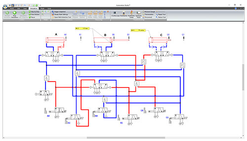
Pneumatic Simulation | Automation Studio™ Professional Edition

APPLICATIONS OF PNEUMATICS AND HYDRAULICS

Hydraulic and Pneumatic Symbols | PDF | Valve | Energy Technology

Pneumax Group | Pneufluid

Simbolos Hidraulicos Din Iso 1219 PDF | PDF | Engines | Valve

SIMBOLOGIA-NEUMATICA-ISO-1219-1.pdf

Simbolos hidraulicos din-iso 1219

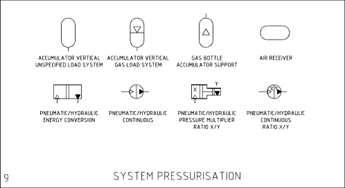
Pneumatic Iso 1219 Symbol Library

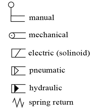
Hydraulic Pneumatic Circuit Symbols - Roy Mech

Pneumatic and Hydraulic Drawing Information

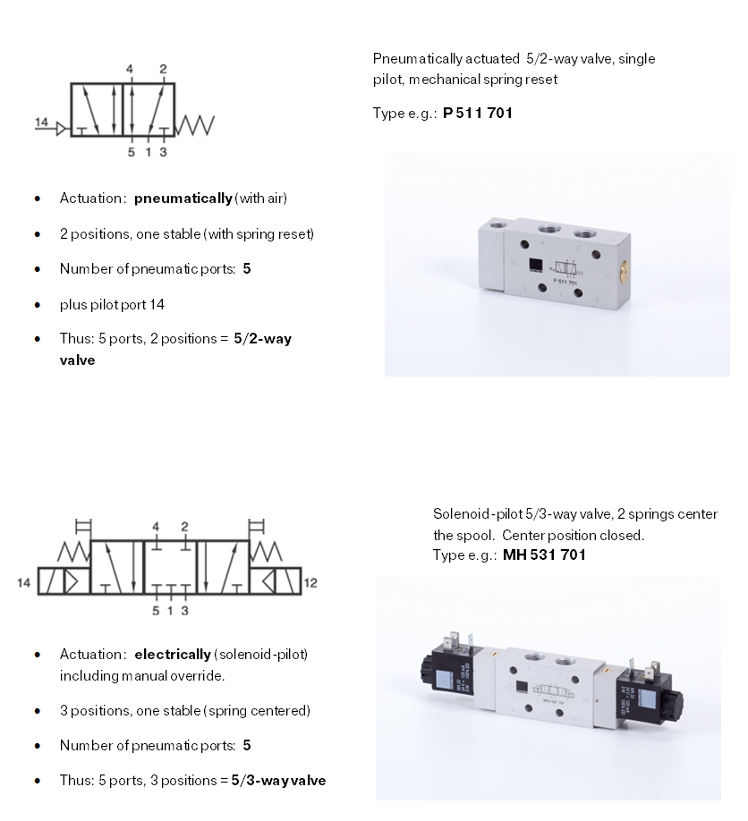
ISO Schemes of directional control valves

How to read hydraulic circuits, schematic hydraulic symbols to DIN ISO 1219

Reference identification to ISO 1219-2 and/or EN

ISO Schemes of directional control valves

Pneumatics Symbols Din ISO 1219 PDF | PDF

ISO 1219-3:2016(en), Fluid power systems and components — Graphical symbols  and circuit diagrams — Part 3: Symbol modules and connected symbols in  circuit diagrams
ISO 1219-3:2016(en), Fluid power systems and components — Graphical symbols and circuit diagrams — Part 3: Symbol modules and connected symbols in circuit diagrams

Reference Identification To ISO 1219-2 And/or EN 81346-2 | PDF | Valve |  Electrical Engineering
Reference Identification To ISO 1219-2 And/or EN 81346-2 | PDF | Valve | Electrical Engineering

Symbols PDF | PDF | Valve | Actuator

Symbology 401 – logic elements

dsi en reference identification iso 1219 en 81346.pdf - Reference  identification to ISO 1219-2 and/or EN 81346-2 Introduction According to  the | Course Hero
dsi en reference identification iso 1219 en 81346.pdf - Reference identification to ISO 1219-2 and/or EN 81346-2 Introduction According to the | Course Hero

ISO Schemes of directional control valves

Pneumatic and Hydraulic Drawing Information